


A computer network is a connection between two or more devices, or nodes, that allows each node to share data.
The organization of nodes in a network is called its Topology. Topology falls into six (6) categories:
Point-to-Point
Daisy Chain
Bus
Ring
Star
Mesh
Point-to-Point
In this topology, two nodes share a connection. It is uncommon to find this type of topology.

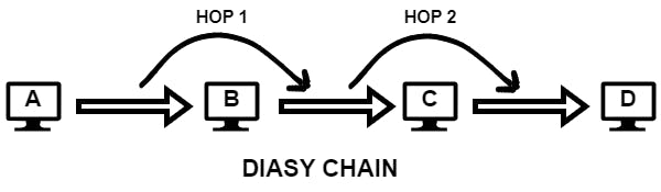
Daisy Chain
A series of point-to-point connections creates a daisy chain. i.e. traffic from node A, destined for node D, must traverse nodes B and C.
Intermediate nodes between an origin node and a destination node are commonly known as Hops. You are unlikely to encounter this topology in a modern network.
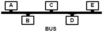
Bus Topology
In this topology, nodes share a common network link. This topology is not common in wired bus networks, but it drives wireless networks. The nodes on a wired network see all the traffic and selectively ignore or accept it. Although wireless clients can see each other's traffic, traffic is usually encrypted.
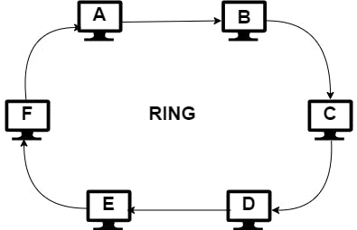
Ring Topology
This is used in some fiber-optic network deployments. It is a closed loop in which data travels in a single direction. Example: Node A could send a message destined for Node E by way of nodes B, C, and D. Nodes B, C, and D retransmit the message until it reaches E. If node C fails to retransmit the message, it will never reach its destination. Because of this design, the slowest node can limit the speed at which data travels.
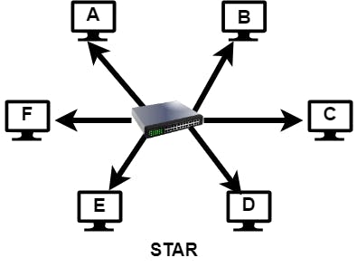
Star Topology
In star topology, a central node has individual point-to-point connections to all other nodes (usually in wired networks). The central node is often a network switch, which is a device that accepts data from the origin nodes and retransmits data to the destination nodes, like a postal service. Adding nodes is a simple matter of connecting them to the switch. Data can traverse only a single hop within this topology.
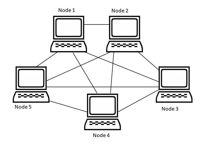
Mesh Topology
In mesh topology, every node has a direct connection to every other node. It eliminates single points of failure but costs and complexity increase as the number of nodes increases.
Bandwidth and Latency
Network bandwidth is the amount of data we can send over a network connection in an interval of time. Example: 100Mbps download - i.e. your internet connection should be able to transfer 100megabits every second from your internet service provider(ISP) to your modem.
Network latency, on the other hand, is a measure of the time that passes between sending a network resource request and receiving a response. An example of latency is the delay that occurs between clicking a link on a website and the site's rendering the resulting page. This happens when the latency is greater than the maximum amount of time your browser will wait for a reply.
Ways to address the most common sources of latency
Reduce both the distance and the number of hops between users and your service by using a content delivery network (CDN) or cloud infrastructure to locate your service near your users.
Optimizing the request and response sizes
Incorporate a caching strategy in your network application.
Open Systems Interconnection (0SI)
OSI serves as a framework for the development of and communication about protocols. Protocols are rules and procedures that determine the format and order of data sent over a network. For example: communication using Transmission Control Protocol (TCP) requires the recipient of a message to reply with an acknowledgment of receipt. Otherwise, TCP may retransmit the message. OSI is less relevant today, but still important in understanding common concepts, such as lower-level networking and routing.
The OSI model consists of 7 Layers.
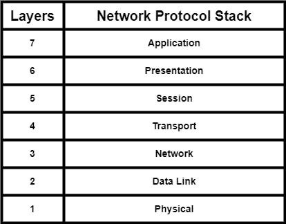
Layer 7 - Application Layer
It is responsible for identifying hosts and retrieving resources. For example web browsers, skype, etc.
Layer 6 - Presentation Layer
It prepares data for the network layer when that data is moving down the stack and it presents data to the application layer when that data moves up the stack. Encryption, decryption, and data encoding are examples.
Layer 5 - Session Layer
It manages the connection life cycle between nodes on a network. It's responsible for establishing the connection, managing connection time-outs, coordinating the mode of operation, and terminating the connection.
Layer 4 - Transport Layer
It controls and coordinates the transfer of data between two nodes while maintaining the reliability of the transfer. Maintaining the reliability of the transfer includes correcting errors, controlling the speed of data transfer, chunking or segmenting the data, retransmitting missing data, and acknowledging received data. Often protocols in this layer might retransmit data if the recipient doesn't acknowledge receipt of the data.
Layer 3 - Network Layer
It is responsible for transmitting data between nodes. It allows you to send data to a network address without having a direct point-to-point connection to the remote node. OSI does not require protocols in this layer to provide reliable transport or report transmission errors to the sender. The network layer is home to the network management protocols involved in routing, addressing, multi-casting, and traffic control.
Layer 2 - Data Link Layer
It handles data transfers between two directly connected nodes. For example, the data link layer facilitates data transfer from a computer to a switch and from the switch to another computer. Protocols in this layer identify and attempt to correct errors on the physical layer.
Layer 1 - Physical Layer
It converts bits from the network stack to electrical, optic, or radio signals suitable for the underlying physical medium and from the physical medium back into bits. This layer controls the bit rate. The bit rate is the data speed limit. A gigabit per second means data can travel at a maximum of 1 billion bits per second between the origin and destination.
A common confusion when discussing network transmission rates is using bytes per second instead of bits per second. We count the number of zeros and ones, or bits, we can transfer per second. Therefore, network transmission rates are measured in bits per second. We use bytes per second when discussing the amount of data transferred.
If your internet service provider(ISP) advertises a 100Mbps download rate, that doesn't mean you can download a 100MB file in one second. Rather, it may take closer to eight seconds under ideal network conditions. It's appropriate to say that we can transfer a maximum of 12.5MB per second over the 100Mbps connection.
TCP/IP Model
The TCP/IP - Transmission Control Protocol and the Internet Protocol - model simplifies OSI's application, presentation, and session layers into a single application layer.
It consists of four named layers:
Application layer
Transport layer
Internet layer
Link layer
Application Layer
It interacts directly with software applications. Most of the software we write uses protocols in this layer and when your web browser retrieves a web page, it reads from this layer of the stack
Common TCP/IP application layer protocols include:
HTTP
FTP - File Transfer Protocol for file transfer between nodes
SMTP - Simple Mail Transfer Protocol - For sending emails to the mail servers
DHCP - Dynamic Host Configuration Protocol
DNS - Domain Name Systems
DHCP and DNS provide the addressing and name resolution services respectively, that allow other application layer protocols to operate.
Transport Layer
It makes sure the data received by the destination is in the correct order, without duplicate data or missing data.
Primary transport layer protocols are:
TCP - Transmission Control Protocol
UDP - User Datagram Protocol
Internet Layer
It is responsible for routing packets of data from the upper layers between the origin node and the destination node, often over multiple networks with heterogeneous physical medium. Internet Protocol Version 4 and 6 (IPV4 and IPV6), Border Gateway Protocol (BGP), Internet Control Message Protocol (ICMP), Internet Group Management Protocol (IGMP), and the Internet Protocol Security (IPsec) suite, provide host identification and routing to TCP/IP's internet layer
Link Layer
The link layer's Address Resolution Protocol (ARP) translates a node's IP address to the Media Access Control (MAC) address of its network interface. The link layer embeds the MAC address in each frame's header before passing the frame on to the physical network.
Thanks for dedicating your time to reading this blog 😊. I hope you learned something new. Don't forget to subscribe and follow for more informative content!